 English
 Français
  Deutsch
 J. Installation Procedures – 2nd Boom Calibration
- Due to the mathematical constraints of the automatic calibration procedure, calibrating a 2nd boom machine sometimes MAY lead to strange inaccuracies of the calculated element lengths. The purpose of the following calibration procedures is to provide recommendations and a dedicated procedure on how to avoid these errors.
- The main differences of calibrating a 2nd boom machine rather than a single boom are the following:
- 10/20 laser pointer shots are required instead of the standard 6/12 laser pointer shots.
- It is necessary to SIGNIFICANTLY change the angles between the main boom and the 2nd boom after EACH laser pointer shot.
- It is important to gain significant angle variances of ALL elements during the 10/20 laser pointer shots.
- The main challenge is to find a procedure which leads to these significant angle variances of all elements, especially the main boom and 2nd boom, which may – depending on the procedure – only run through angle variances of 10-20°, which usually isn’t sufficient for proper calibration results and accuracies.
- In the case of LARGE 2nd boom machines with 2nd boom lengths of 3.65 – 5.49m, a free setup of the laser pointer using the magnetic mount rather than the two poles (or an elevating tripod) is recommended. Generally speaking, the larger the laser pointer low/high height difference, the more accurate the calibration results will be.
- Remove the bucket prior to machine calibration.
- Lower the machine’s dozer blade, if it has one, to stabilize the chassis.
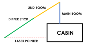
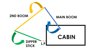
- In the lower laser pointer position, prior to the first (1) shot, fully fold in the 2nd boom and fully reach out with the dipper stick:
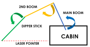
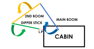
5. Prior to the second (2) shot, unfold the 2nd boom approximately 25% of the cylinders length and pull in the dipper stick approximately 10%. Lower the main boom to catch the laser dot:
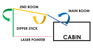
6. Continue progressively up to shot five (5) unfolding the 2nd boom approximately 25% of the cylinder’s length each time to reach the fully extended orientation. Pull in the dipper stick approximately 10% each time to arrive at an approximately vertical position. Lower the main boom to catch the laser dot:
7. Prior to shot six (6), fold in the 2nd boom approximately 25% of the cylinder’s length. Pull in the dipper stick approximately 10%. Lower the main boom to catch the laser dot:
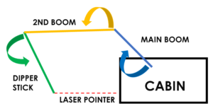
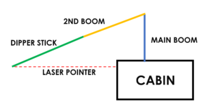
8. Continue progressively up to shot ten (10), folding in the 2nd boom approximately 25% of the cylinder’s length each time to reach a fully folded orientation. Pull in the dipper stick approximately 10% each time to arrive almost horizontal. Lower the main boom to catch the laser dot:
9. Repeat the procedure in the high laser pointer level. You may have to open the 2nd boom slightly to achieve the laser catch, depending on the machine’s geometry:
10. Continue progressively up to shot ten (10), folding the 2nd boom approximately 25% of the cylinder’s length each time to reach a fully folded orientation. Pull in the dipper stick approximately 10% each time to arrive almost horizontal. Lower the main boom each time to catch the laser dot:
Due to the significant angle variances of ALL elements (main boom, 2nd boom, dipper stick), AND the significant angle changes between the 2nd boom & main boom, you will consequently gain MUCH BETTER results. The comparison of calculated to measured element lengths will be almost spot-on.