English
 Français
  Deutsch
 Welcome to our Support Center
E. Installation Procedures – Dipper Stick (Combo) Sensor
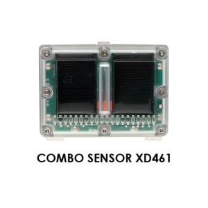
Dipper Stick (Combo) Sensor
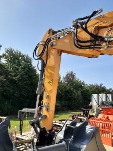
- The Combo Sensor will need to be located on the dipper as low as possible. The higher the Sensor is located the more the boom and dipper has to be dropped to catch the laser beam. Be aware of the location of hoses and pipes that may inhibit a clear line of sight to the Sensor when using the laser catch function.
- For more accurate calibration and ease of setup regarding the laser catch function you may want to consider installing the Combo Sensor using the following directions. This will allow you to manually enter accurate measurements into the laser calibration setup stage and will maximize the accuracy of the laser catch function.
- You will want to offset the placement of the Combo Sensor counter-clockwise slightly 15° – 30° from when the dipper stick is set at 90° to the ground. This will maximize the reception area of the Combo Sensor and help with catching the laser beam.
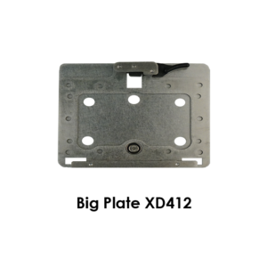
- Suitably clean the area with Brake Cleaner and wipe dry. Clean the surface of the boom as well as the back of the mounting bracket with the 3M VHB wipes after completely cleaning the surface. They are not intended to clean but they accelerate setting the glue of the 3M tape. Attach the 3M double sided tape to the bracket and then stick your sensor plate on firmly and press for 30 seconds. The adhesive bond will strengthen over time.

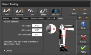
Recommended calibration of the Laser Receiver
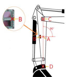
- Using a magnetic plumb bob or a string and magnets, create a line between the center points of the dipper stick/main boom pivot pin (C) and the dipper stick/bucket pivot pin (D). (Line C-D)
- On the bottom 1/3 of the dipper stick place the Combo Sensor so that the very center of the photo cell array (B) is on this line (C-D). Rotate the sensor counter-clockwise slightly by 15° – 30°.
- Take a measurement from the center of the top pin (C) to the center of the Combo Sensor (B) staying on the string line. This will be the A-C measurement. The A-B measurement will be 0. Enter these measurements via the System Settings menu once the main iDig calibration steps have been completed.