 English
 Français
  Deutsch
 Welcome to our Support Center
B. Hardware Installation
Step 1 – Installation of LED Display and Control Box
The machine needs to be powered OFF
- Before plugging in the cables, find suitable locations to mount the LED Cradle and Control Box Cradle
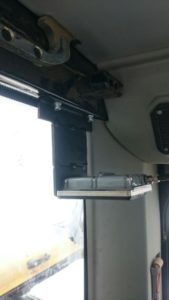
- The LED Display should be put on the front window so that is in your field of vision of the working area outside.
- If there is no window, you’ll need to use the optional C Clamp to mount it on the bar.
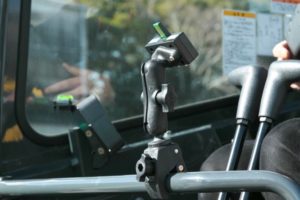
- The Control Box is usually mounted onto the right-hand side window and at a distance that is comfortably reached by hand.
- Allow clearance for the front window to be opened or slid up into the roof.
- Use window cleaner to clean both the glass and the suction cup mounts to achieve good adhesion.
- Attach cables to the LED and Control Box Cradles. Secure the cables with conduit, cable ties, etc.
- DO NOT PLUG IN POWER until AFTER the 2D Sensor is installed.
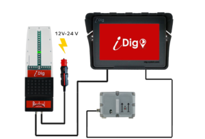
Complete Cabling setup

Control Box Setup Optional C Clamp
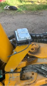
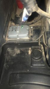
Step 2 – Installation of 2D Sensor
Locating a suitable spot to install the 2D Sensor is worthwhile taking some time to get right. You are looking for a place that:
- Is accessible – the Sensor is able to be reached and removed from its mounting plate with the removal key without interference.
- Sensor will be level and facing forward.
- Arrows on the top of the sensor need be installed facing toward the front of the cab.
- The Sensor ideally needs to be placed in a spot that is level to the floor of the cab.
- Installing the 2D Sensor on a tilt is acceptable if a level location is unable to be found.
- A maximum angle of ±30° on both axis is OK.
- Is free from vibration
- Avoid plastic molding that is removable as this can vibrate when the machine is running.
- Has adequate space for cable and plug
- The communication cable is not under tension. Use an extra XD418 cable if more length is required.
- The cable and plug into the sensor sticks out approximately 2.5 cm from the edge of the sensor. 5 – 8cm clearance is desirable to avoid complications with the cable bending to sharply.
- Will not be subject to knocks or damage
- Avoid areas where tools are commonly stored.
- On some machines, under the floormats to the side of the operators feet is the only location. Take care to make a safe place where the Sensor and cable will not be affected.
Set-up for Backhoe only