 English
 Français
  Deutsch
 Welcome to our Support Center
O. Installation Procedures – Tilt Bucket Calibration
Install the Sensors
- Install the Triangle Holder on the lower part of the tilt axis as shown on these pictures:
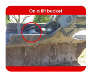
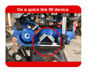
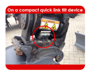
- The Triangle Holder may be setup in ANY position and orientation!
If there is no space available to setup the Triangle Holder, it is possible to install the 2 Mini Sensors without it. It is mandatory to proceed by the following 4 rules:
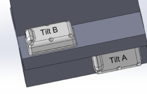
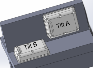
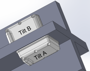
- #1 – The planes of the two Sensors MUST be perpendicular to each other:
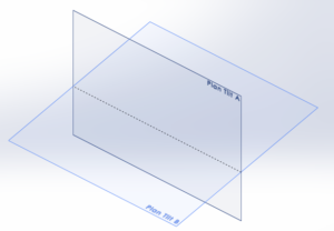
- #2 – The longer sides of the Sensor’s base plates MUST remain collinear:
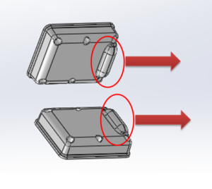
- #3 – The “bumps” with the radio antennas underneath MUST be placed on the same side:
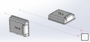
- #4 – Tilt A should not be mixed-up with Tilt B. The following rules shall be applied to install the Sensors:
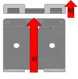
- Choose one of the two plates and imagine an arrow from the “ears” and going towards the blade spring
- On the second plate, imagine an arrow from the back of the plate to the top of the plate.
- If the two arrows are in the same direction, then that plate is for Tilt B.
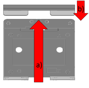
- If the two arrows are opposite to each other, then that plate is for Tilt A.
- Some examples of a Triangle Holder free setup:
Calibration on a New Machine
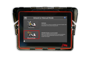
- Perform a complete machine calibration:

![]()
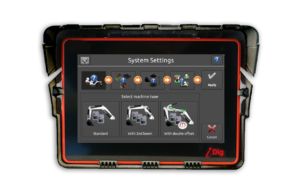
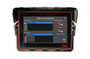
- Select the machine’s configuration
- Continue by following the instructions on the screen:
![]()
- Make sure you have the Tilt A & Tilt B Sensors paired to the system and placed on the correct plates.
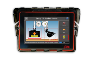
- Open the bucket to horizontally level the tilt axis using a spirit level.
- Tilt the bucket left/right to horizontally level the bucket blade using a spirit level.
- Click on “Next”.
![]()
- Slowly close the bucket between a range of 35°-55°.
- Tilt the bucket left/right to horizontally level the bucket blade using a spirit level.
- Click on “Next”.
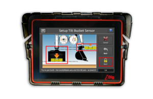
![]()
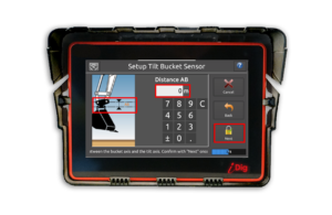
- Close the bucket to horizontally level the tilt axis using a spirit level.
- Measure the distance between the bucket pivot pin and the tilt axis (line AB).
- Enter this value into the system using the correct unit length.
- Click on “Next”.

![]()
- Verify/enter the bucket width. Make sure you are using the correct unit length.
- Click on “Next”.
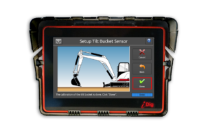
- The calibration of the tilt bucket is done!
- Click on “Done”.
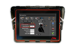
Calibration on an Existing Machine
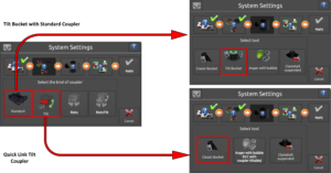
- To add support for tilt on an already calibrated machine, select an already calibrated bucket and go into “System Settings”:
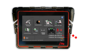
- Select “Calibrate Tilt of Bucket” if the actually attached and selected bucket has it’s own tilt mechanism. When you select this bucket from the bucket menu, the tilt function will be available. Each bucket will need to be individually calibrated
- Select “Calibrate Tilt of Quicklink” if it is an Engcon, Powertilt or equivalent system. The tilt function only needs to be calibrated once, all registered buckets will have the tilt function.
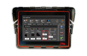
Machine Parameters
- No tilt available

![]()
- On the “Buckets” tab the “Tilt” option is unchecked.

- On the “Quick Link” tab the “Tiltable Quicklink” option is unchecked.
NOTE – The Tilt Calibration is not available in Manual Mode. See previous instructions to launch a Tilt Bucket Calibration.
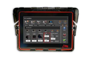
- Tilt on bucket(s)
![]()
- On the “Buckets” tab the “Tilt” option is checked.
- On the “Quick Link” tab the “Tiltable Quicklink” option is unchecked.
NOTE – To redo the tilt calibration of this bucket, remove the corresponding tilt calibration by un-checking the “Tilt” box. Then you can re-run a Tilt Calibration.
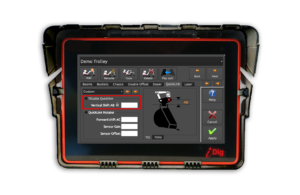
- Quick link tilt
![]()
- On the “Buckets” tab the “Tilt” option is checked.
- On the “Quick Link” tab the “Tiltable Quicklink” option is checked.
NOTE – By un-checking the “Tiltable Quicklink” box option you’ll remove the tilt calibration for all buckets.