 English
 Français
  Deutsch
 Welcome to our Support Center
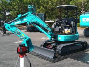
R. Installation Procedures – Dozer Calibration
- The Grade-to-Blade feature REQUIRES that your machine have the Big Combo Sensor installed and paired with the system instead of the standard Combo Sensor.
- There must also be a Mini Sensor installed and paired with the system on one of the dozer blade arms.
- To replace your Standard Combo Sensor with the Big Combo Sensor without having to recalibrate the whole machine, follow the instructions. Otherwise, continue with the Calibration procedures after the star.

Standard Combo Sensor
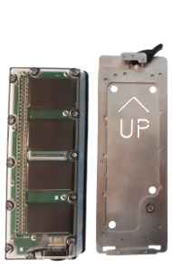
Big Combo Sensor
Big combo replacement
- Do not remove the Standard Combo Sensor yet.
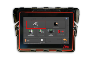
- Start your excavator and the iDig system.
- Touch anywhere on the Main Screen to have the icons fly in from the side. Click on the Sensor Symbol.
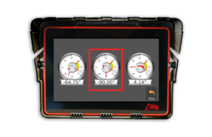
- Place the Dipper Stick in a Vertical position. The Dipper Stick Sensor’s value must be as close to -90.00° as possible
![]()
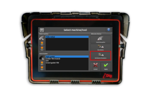
- Go to Machine Parameters
![]()
![]()
![]() Take care to select the right machine
Take care to select the right machine
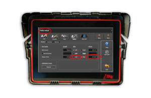
- Select the side where the Big Combo is to be installed
- Click on the “Offset” value
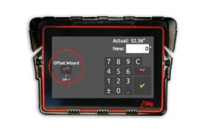
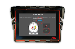
- Click on “Offset Wizard”.
- Remove the old Combo Sensor.
- Install the new Big Combo Sensor plate but do not attach the sensor yet.
- The Sensor Symbol appears missing (red circle). Long press the symbol and install the Big Combo Sensor in order to pair it to the system.
- Press “Validate”.
- Ensure that the blue slider is on “Vertical”.
- Click on Validate.
- Done, the system is now calibrated with your new Big Combo Sensor!

DO NOT FORGET TO CALIBRATE THE LASER RECEIVER OF YOUR BIG COMBO
![]()
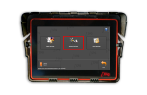
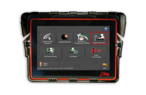
- Enter “System Settings” and then select “Dozer with laser“.
![]()
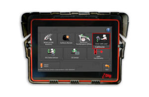
- Click on “Calibrate”.
- Note – If this menu does not appear, ensure that the Big Combo Sensor is detected by the radio.
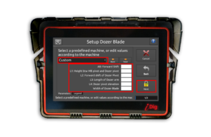
- Select your machine from the drop-down menu. If your machine is not listed then you will need to make the following measurements:
- AB – Forward Shift distance between main boom/chassis pivot point and center of rotation of the machine. Same measurement as the AB for the 2D calibration.
- L1 – Height between main boom pivot and dozer pivot.
- L2 – Distance between the blade pivot and the center of rotation of the machine.
- L3 – Length of the blade front tip and the blade pivot.
- L4 – Distance between the blade pivot and the bottom of the tracks (ground).
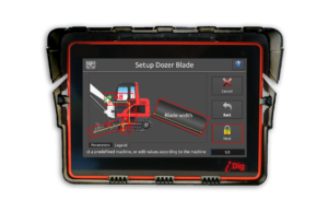
- Width of the dozer blade.
- Click on “Next”.
![]()
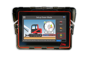
- Select which side of the dozer blade arm the Sensor has been installed. Relevant to the direction that the plastic cover of the Sensor is facing.
- Place the blade on the same flat surface as the tracks are on.
- IMPORTANT – This final step should be done on solid, level ground such as asphalt or concrete!
- Click on “Next”.

- The calibration of your dozer blade is complete! Click on “Done”.
Dozer Fine Tuning:
After having thoroughly validated each calibration procedure (booms, then bucket, then 2D and then laser in many positions), a depth difference may persist between the teeth of the bucket and the dozer blade relative to the ground.
To remove this difference, follow the recommended procedure:
- Set L1 to zero.
- Enable Dozer mode.
- Configure the laser by using the bucket procedure: put the bucket on a surveyor stake and set the depth to zero, then catch the laser.
- Continue the initialization process of the dozer (no slope).
- Move your excavator and put the blade on the surveyor stake and adjust your dipperstick to catch the laser again.
- The depth on the blade is the value L1 that you must enter into the Machine Parameters of Dozer.